From a digital path to a physical drawing
I designed an Arduino-controlled drawing machine using stepper motors and driver boards. The aim was to move a pen according to programmed instructions and draw geometric shapes on paper.
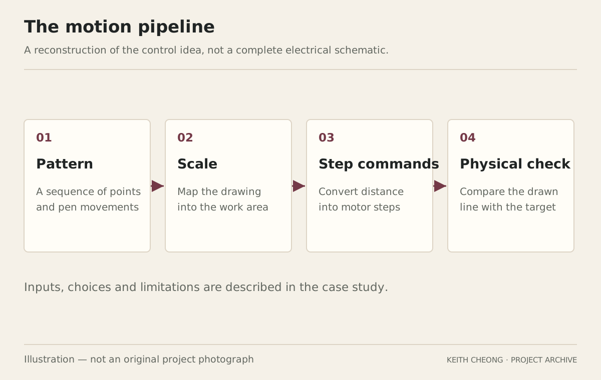
The recorded work began with square-drawing tests. I then explored how diagonals, circles and other patterns could be represented as sequences of movements. This joined hardware assembly, C++ control logic and coordinate calculations in one small system.
The scale problem
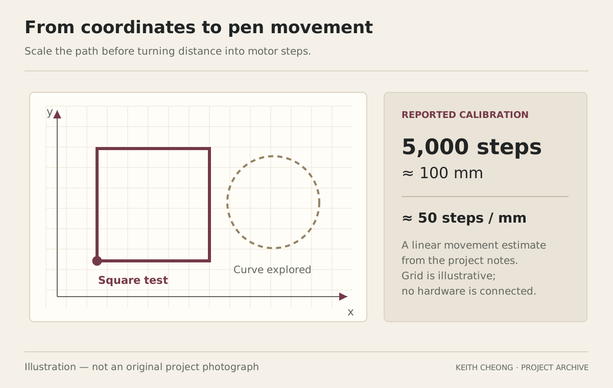
A shape that fits on a computer screen does not automatically fit a machine's travel range. Some patterns extended beyond the available movement area. I worked on the coordinate ratio, number of motor steps and movement boundaries to make the output fit.
The archive's approximate calibration, 5,000 steps over 100 mm, corresponds to about 50 steps per millimetre for that tested movement. It is a reported linear calibration, not a universal specification for every 28BYJ-48 mechanism.
What the reconstruction demonstrates
The browser demo makes a path and its working area visible. It is intended to explain scaling and motion planning without presenting a simulation as a new physical test. Motor load, backlash, missed steps and pen pressure are outside this visual model.
The listed pins and settings are preserved as historical notes. They should not be treated as a complete wiring diagram for an unidentified Arduino board or mechanical assembly.
What I took from it
Debugging a robot meant looking at both code and movement. The most useful question was not just whether the programme ran, but whether a requested distance matched the line drawn on paper.
- Translate coordinates into motor movement.
- Check scale against the available travel area.
- Use a simple shape as a repeatable calibration test.